


High precision navigation system is the core equipment of aircraft navigation control and precise attack of its weapon system. Its mainstream schemes include platform schemes and strapdown schemes.With the development of strapdown inertial technology and optical gyro, strapdown has been widely used in the airborne field with its advantages of high reliability, light and small size, low power consumption and low cost[1-4].At present, airborne strapdown navigation system is a combination of laser gyro strapdown navigation system and fiber optic gyro strapdown navigation system.Among them, Northrop Grumman’s LN-100G, Honeywell’s H-764G laser gyro strapdown navigation system and Northrop Grumman’s LN-251 fiber optic gyro strapdown navigation system have been widely used in the American fighter aircraft fleet[1].Northrop Grumman Company developed the LN-251 navigation system for helicopter with the important symbol of high precision fiber optic gyro, and then developed the LN-260 to adapt to aircraft navigation.The LN-260 was selected by the U.S. Air Force for the avionics upgrade of the F-16 multinational fighter fleet.Prior to deployment, the LN-260 system was tested to achieve a position accuracy of 0.49n mile (CEP), a northbound velocity error of 1.86ft/s (RMS), and an eastbound velocity error of 2.43ft/s (RMS) in a highly dynamic environment.Therefore, the optical strapdown inertial navigation system can fully meet the operational requirements of the aircraft in terms of navigation and guidance capability[1].
Compared with laser gyro strapdown navigation system, fiber optic gyro strapdown navigation system has the following advantages: 1) it does not need mechanical jitter, simplifies the system structure and the complexity of vibration reduction design, reduces the weight and power consumption, and improves the reliability of navigation system;2) The precision spectrum of fiber optic gyro covers tactical level to strategic level, and its corresponding navigation system can also form a corresponding navigation system spectrum, covering everything from attitude system to the navigation system for long-range long-endurance aircraft;3) The volume of fiber optic gyroscope directly depends on the size of fiber ring. With the mature application of fine diameter fiber, the volume of fiber optic gyroscope with the same accuracy is getting smaller and smaller, and the development of light and miniaturization is an inevitable trend.
Overall design scheme
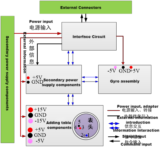
The airborne fiber optic gyro strapdown navigation system fully considers the system heat dissipation and photoelectric separation, and adopts the “three-cavity” scheme[6,7], including IMU cavity, electronic cavity and secondary power cavity. The IMU cavity consists of the IMU body structure, optical fiber sensing ring and quartz flexible accelerometer (quartz plus meter);The electronic cavity consists of a gyro photoelectric box, a meter conversion board, a navigation computer and interface board, and a sanitation guide board;The secondary power cavity comprises a packaged secondary power module, EMI filter, charge-discharge capacitor.The gyro photoelectric box and the optical fiber ring in the IMU cavity together constitute the gyro component, and the quartz flexible accelerometer and the meter conversion plate together constitute the accelerometer component[8].
The overall scheme emphasizes the separation of photoelectric components and the modular design of each component, and the separate design of optical system and circuit system to ensure the overall heat dissipation and the suppression of cross interference.In order to improve the debuggability and assembly technology of the product, connectors are used to connect the circuit boards in the electronic chamber, and the optical fiber ring and accelerometer in the IMU chamber are debugged respectively. After forming the IMU, the whole assembly is carried out.
The circuit board in the electronic cavity is the gyro photoelectric box from top to bottom, including the gyro light source, detector and front discharge circuit;The table conversion board mainly completes the conversion of the accelerometer current signal to the digital signal;Navigation solution and interface circuit includes interface board and navigation solution board, interface board mainly completes synchronous acquisition of multi-channel inertial device data, power supply interaction and external communication, navigation solution board mainly completes pure inertial navigation and integrated navigation solution;The guide board mainly completes the satellite navigation, and sends the information to the navigation solution board and the interface board to complete the integrated navigation.The secondary power supply and the interface circuit are connected through the connector, and the circuit board is connected through the connector.
Key technologies
1. Integrated design scheme
The airborne fiber optic gyro navigation system realizes the aircraft’s six degrees of freedom motion detection through the integration of multiple sensors.Three axis gyro and three axis accelerometer can be considered for high integration design, reduce power consumption, volume and weight.For the fiber optic gyro component, it can share the light source to carry out the three-axis integration design;For the accelerometer component, quartz flexible accelerometer is generally used, and the conversion circuit can only be designed in three ways.There is also the problem of time synchronization in multi-sensor data acquisition. For high dynamic attitude update, time consistency can ensure the accuracy of attitude update.
2. Photoelectric separation design
The fiber optic gyro is a fiber optic sensor based on the Sagnac effect to measure angular rate.Among them, the fiber ring is the key component of the sensitive angular speed of the fiber gyroscope. It is wound by several hundred meters to several thousand meters of fiber.If the temperature field of the optical fiber ring changes, the temperature at each point of the optical fiber ring changes with time, and the two beams of light wave pass through the point at different times (except the middle point of the optical fiber coil), they experience different optical paths, resulting in a phase difference, this non-reciprocal phase shift is indistinguishable from the Sagneke phase shift caused by rotation.In order to improve the temperature performance of the fiber optic gyroscope, the core component of the gyroscope, the fiber ring, needs to be kept away from the heat source.
For the photoelectric integrated gyroscope, the photoelectric devices and circuit boards of the gyroscope are close to the optical fiber ring. When the sensor is working, the temperature of the device itself will rise to some extent, and affect the optical fiber ring through radiation and conduction.In order to solve the influence of temperature on the optical fiber ring, the system uses a photoelectric separation of the optical fiber gyroscope, including optical path structure and circuit structure, two kinds of structure independent separation, between the fiber and the waveguide line connection.Avoid the heat from the light source box affecting the fiber heat transfer sensitivity.
3. Power-on self-detection design
Fiber optic gyro strapdown navigation system needs to have the electrical performance self-test function on the inertial device.Because the navigation system adopts pure strapdown installation without transposition mechanism, the self-test of inertial devices is completed by static measurement in two parts, namely, device-level self-test and system-level self-test, without external transposition excitation.
ERDI TECH LTD Soluzioni per le specifiche tecniche
|
Number |
Product Model |
Weight |
Volume |
10min Pure INS |
30min Pure INS |
||||
|
Position |
Heading |
Attitude |
Position |
Heading |
Attitude |
||||
|
1 |
F300F |
< 1kg |
92 * 92 * 90 |
500m |
0.06 |
0.02 |
1.8 nm |
0.2 |
0.2 |
|
2 |
F300A |
< 2.7kg |
138.5 * 136.5 * 102 |
300m |
0.05 |
0.02 |
1.5 nm |
0.2 |
0.2 |
|
3 |
F300D |
< 5kg |
176.8 * 188.8 * 117 |
200m |
0.03 |
0.01 |
0.5 nm |
0.07 |
0.02 |
Post time: May-28-2023