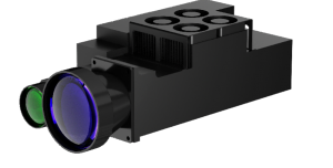
100mJ Laser Target Designator


TECHNICAL SPECIFICATIONS
|
Wavelength |
1.064μm |
|
Output energy |
total temperature: 100mJ ~ 120mJ, average output energy ≥110mJ, single pulse energy > 100mJ (2 seconds before removal) |
|
Adjacent pulse energy fluctuation range |
≤8% |
|
Beam dispersion Angle |
0.15mrad (the acceptance method adopts hole-hole method, and the ratio of hole-hole to hole-free is not less than 86.5%) |
|
Spatial pointing instability of beam |
≤0.03mrad (1σ) |
|
Irradiation frequency |
accurate coding 45ms~56ms (check code 20Hz) |
|
Pulse cycle accuracy |
≤±2.5μs |
|
Pulse width |
15ns±5ns |
|
Irradiation time |
no less than 90s, interval 60s, or no less than 60s, interval 30s, 4 cycles of continuous irradiation at room temperature and low temperature, 2 cycles of continuous irradiation at high temperature |
|
Ranging range |
the minimum value is not more than 300m, the maximum is not less than 35km (23km visibility, medium atmospheric turbulence, for 2.3m×2.3m target, target reflection coefficient is greater than 0.2) |
|
Irradiation distance |
for 2.3m×2.3m target, not less than 16km |
|
Normal temperature power-up preparation time |
<30 seconds |
|
Low temperature power-up preparation time |
<3 minutes |
|
Service life |
≥2 million times |
|
Ranging counting range |
200m ~ 40km |
|
Ranging accuracy |
±2m |
|
Accurate measurement rate |
≥98% |
|
Ranging frequency |
1Hz, 5Hz, 10Hz, 20Hz |
|
Installation datum and laser transmission optical axis of non-parallel |
≤0.5mrad |
|
Installation datum flatness |
0.01mm (design guarantee) |
|
Insulation resistance |
under standard atmospheric pressure, the insulation resistance value of the specified measuring point should conform to the provisions of Table 1 |
Table 1 specifies the insulation resistance values of the measuring points
|
Serial number |
Environmental conditions |
Insulation resistance |
Megohm meter output voltage |
|
1 |
Standard atmospheric conditions |
20 m Ω or greater |
100V |
u External logo (including product number) should be fixed firmly, clear, complete and easy to identify.
PRINCIPLE OF RANGING
After the laser imager is started, the laser pulse with a periodic frequency of 1Hz is emitted, which reaches the measured target through the transmitting antenna. Most of the beam is absorbed or diffusely reflected by the target, while a very small part of the beam returns to the receiving antenna and converges on the detector module. The detector module samples the reflected signal and obtains the distance information of the measured target through an algorithm.
Examples of calculation:
Measurement time (one round trip) =10us
Propagation time (one way) =10us/2=5us
Ranging distance = Light speed × travel time =300000km/s×5us=1500m
RANGING CAPABILITY IN DIFFERENT VISIBITY
Atmospheric visibility has a great impact on the ranging performance of laser photometer. Please refer to Figure 2 for the ranging capability of this product in different visibility.
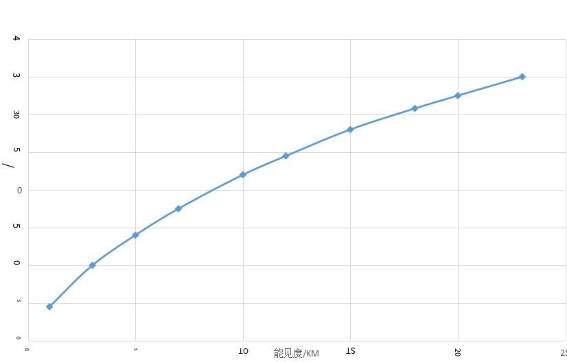
Figure 2 The relationship between the ranging ability of laser photometer and atmospheric visibility
HUMAN EYE SAFETY
The laser rangefinder uses a laser source in the band of 1064nm. When using the laser in this band, it is necessary to avoid the outgoing beam directly into the human eye as far as possible to prevent human eye injury.
MECHICAL INTERFACE
The mechanical interface of the laser photometer consists of 3 through holes, which are fixed to the installation platform by 3 M5 screws. The dimensions of the mechanical and optical interfaces are shown in Figure 3 below.
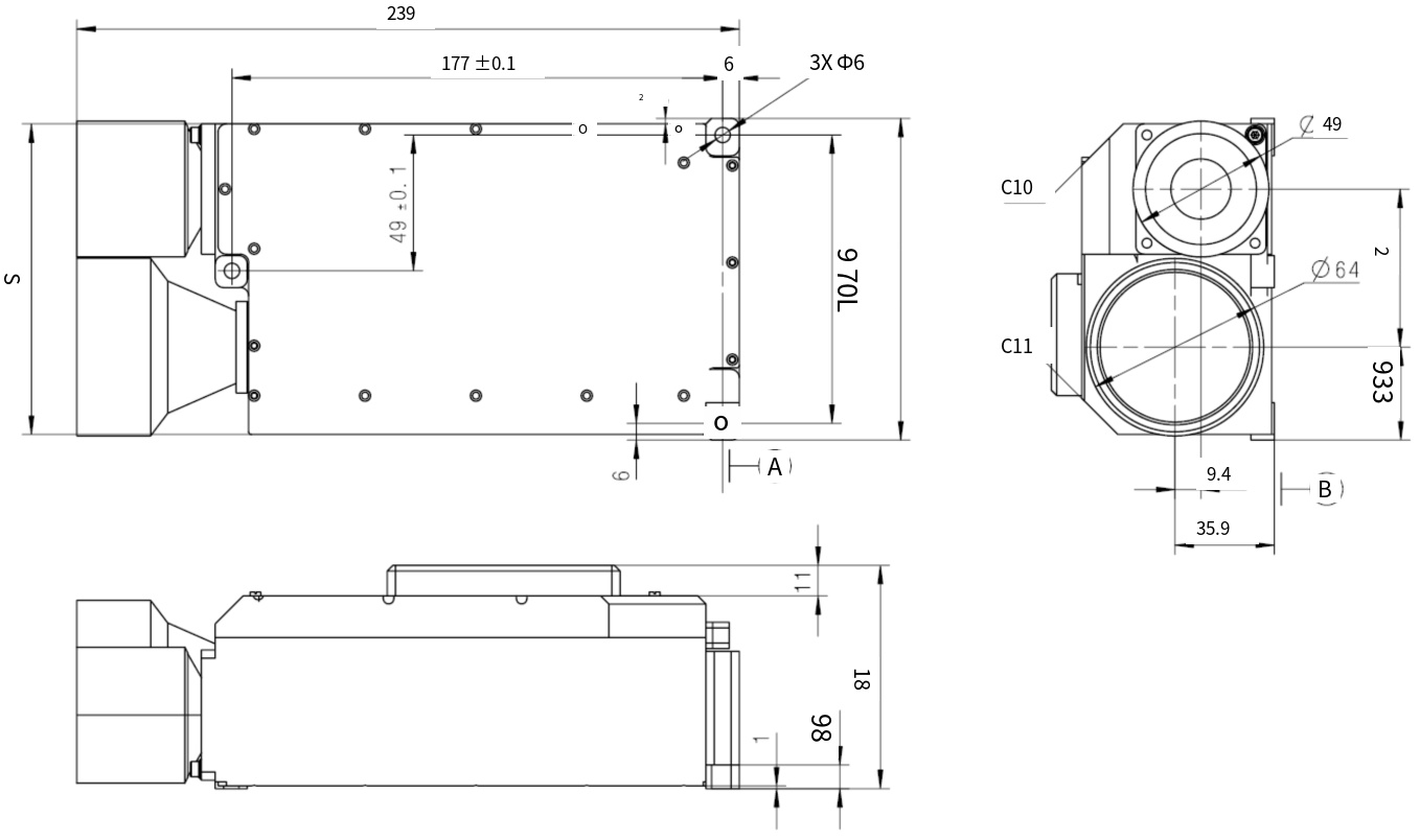
Figure 3 shows the mechanical and optical interfaces