Drive circuit 1
Drive circuit 1
Parameters
|
Parameters |
Specification |
|
Power supply |
DC12V(24V it can be customizable) |
|
Interface |
RS422 |
|
Drivers |
Maximum pulse width: 3ms(it can be set by serial port command) |
|
Driving control |
It can control drive frequency and switch by RS422. |
|
Driving current |
100μJ laser: 6A /200μJ laser: 12A/300μJ laser: 13A-15A 400/500μJ laser: 14A-16A |
|
Driving voltage |
2V |
|
Discharge frequency |
≤10Hz |
|
Power supply mode |
DC 5V |
|
Trigger mode |
External trigger |
|
External interface |
TTL(3.3V/5V) |
|
Pulse width(Electric discharge) |
It depends on external signal,<3ms |
|
Current stability |
≤1% |
|
Storage temperature |
-55~75°C |
|
Operating temperature |
-40~+70°C |
|
Dimension |
26mm*21mm*7.5mm |
Interface
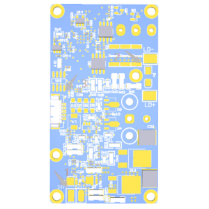
LD+ and LD- connect to positive pole and negative pole respectively. It shown as following:

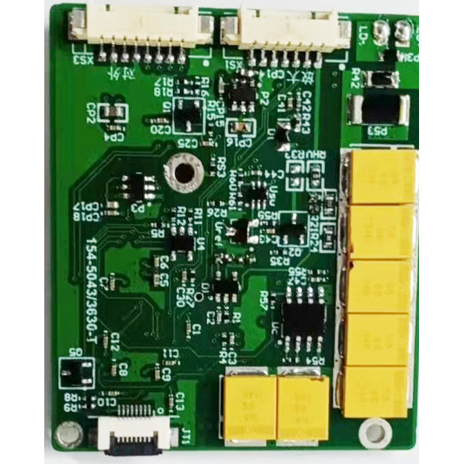
External interface

As shown above, XS3 is an external interface, it can connect to external power supply and upper computers. Connection information as shown as follows:

|
1 |
RS422 RX+ |
Interface |
|
2 |
RS422 RX- |
Interface |
|
3 |
RS422 TX- |
Interface |
|
4 |
RS422 TX+ |
Interface |
|
5 |
RS422_GND |
GND |
|
6 |
VCC 12V |
12V power supply |
|
7 |
GND |
Power supply GND |
Form:RS422, Baud rate:115200bps
Bits:8 bits(a start bit,a stop bit, no parity). Data consists of header bytes, commands, length of bytes, parameters and parity check bytes.
Communication mode:master-slave mode. An upper computer sends orders to the drive circuit, the drive circuit receive and carry out orders. In working mode, the drive circuit will send data to an upper computer periodically. Details of orders and forms as shown as following.
1) An upper computer sends
Table 1 Sending form
|
STX0 |
CMD |
LEN |
DATA1H |
DATA1L |
CHK |
Table 2 Sending form specification
|
NO. |
Name |
Specification |
Code |
|
1 |
STX0 |
Start mark |
55(H) |
|
2 |
CMD |
Command |
Shown as table 3 |
|
3 |
LEN |
Bytes length (except STX0, CMD and checkout bits) |
/ |
|
4 |
DATAH |
Parameters |
Shown as table 3 |
|
5 |
DATAL |
||
|
6 |
CHK |
XOR checkout (Except check bytes, all the bytes can have XOR checkout) |
/ |
Table 3 Command and bits specification
|
NO. |
Commands |
Specification |
Bytes |
Note. |
Length |
Example |
|
1 |
0×00 |
Stand by (continuous working stops) |
DATAH=00(H) DATAL=00(H) |
Drive circuit stops |
6 Bytes |
55 00 02 00 00 57 |
|
2 |
0×01 |
Single working |
DATAH=00(H) DATAL=00(H) |
|
6 Bytes |
55 01 02 00 00 56 |
|
3 |
0×02 |
Continuous working |
DATAH=XX(H) DATAL=YY(H) |
DATA= working cycle, unit: ms |
6 Bytes |
55 02 02 03 E8 BE (1Hz operating) |
|
4 |
0×03 |
Self-check |
DATAH=00(H) DATAL=00(H) |
|
6 Bytes |
55 03 02 00 00 54 |
|
5 |
0×06 |
Total numbers of light output |
DATAH=00(H) DATAL=00(H) |
Total numbers of light output |
6 Bytes |
55 06 02 00 00 51 |
|
13 |
0×20 |
Overtime setting of continuous operating |
DATAH=00(H) DATAL=00(H) |
DATA=overtime of continuous operating, unit: min |
6 Bytes |
55 20 02 00 14 63 (20min) |
|
12 |
0xEB |
NO. check |
DATAH=00(H) DATAL=00(H) |
Circuit board NO. check |
66Bytes |
55 EB 02 00 00 BC |
2)An upper computer receives
Table 4 Receiving form
|
STX0 |
CMD |
LEN |
DATAn |
DATA0 |
CHK |
Table 5 Receiving form specification
|
NO. |
Name |
Specification |
Code |
|
1 |
STX0 |
Start mark |
55(H) |
|
2 |
CMD |
Command |
Shown as table 6 |
|
3 |
LEN |
Bytes length (except STX0, CMD and checkout bits) |
/ |
|
4 |
DATAH |
Parameters |
Shown as table 6 |
|
5 |
DATAL |
||
|
6 |
CHK |
XOR checkout (Except check bytes, all the bytes can have XOR checkout) |
/ |
Table 6 Command and bits specification
|
NO. |
Commands |
Specification |
Bytes |
Note. |
Length |
|
1 |
0×00 |
Stand by (continuous working stops) |
D1=00(H) D0=00(H) |
|
6 Bytes |
|
2 |
0×01 |
Single working |
D3 D2 D1 D0 |
|
8 Bytes |
|
3 |
0×02 |
Continuous working |
D3 D2 D1 D0 |
|
8 Bytes |
|
4 |
0×03 |
Self-check |
D7 ~D0 |
D5-D4: -5V, unit:0.01V D7-D6:+5V, Unit: 0.01V(<450V is under-voltage) |
13 Bytes |
|
6 |
0×06 |
Total numbers of light output |
D3~D0 |
DATA=Total numbers of light output(4 bytes, the most significant byte is in front) |
8 Bytes |
|
9 |
0xED |
overtime operating |
0×00 0×00 |
Laser is under protection and stops working |
6 Bytes |
|
10 |
0xEE |
Checkout error |
0×00 0×00 |
|
6 Bytes |
|
11 |
0XEF |
0×00 0×00 |
|
6 Bytes |
|
|
18 |
0×20 |
overtime setting of continuous operating |
DATAH=00(H) DATAL=00(H) |
DATA=overtime of continuous operating, unit: min |
6 Bytes |
|
12 |
0xEB |
NO. check |
D12…… D0 |
D10 D9 NO. of drive circuit D8 D7 software version |
17 Bytes |
|
Note:Undefined data bytes/bits. Default value is 0. |
|||||