Laser Rangefinder Module 15K1A

Product description
1.1 Product functions
- Laser ranging function;
- Power on and temperature collection function;
- With distance gating function;
- Equipped with first/last target ranging function;
- Has self-checking function;
- Equipped with serial port update program function.
1.2 Product description
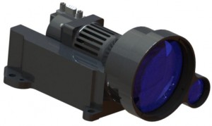
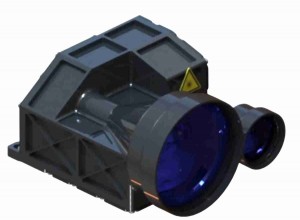
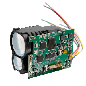
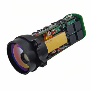
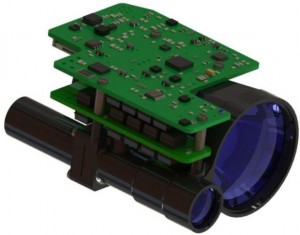
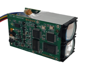
The schematic diagram of the LRF15K1A laser range finder product is shown in Figure 1, which mainly consists of the following parts:
- Receiving and transmitting components;
- Control and information processing circuit components;
- Laser power circuit components.

Figure 1 Schematic diagram of product composition
1.3 Mechanical and optical interfaces
The overall dimensions of the optical-mechanical interface of the laser rangefinder are shown in Figure 2.

Figure 2 Optical-mechanical interface diagram
1.4 Electrical interface
The laser range finder connector socket model is J30J-9ZKP, which includes the laser range finder power supply and communication signals. The standard RS422 communication interface is used to communicate with the system. The power supply and communication port pin definitions of the laser rangefinder are shown in Table 1.
Table 1 Definition of power supply and communication port pins on the rangefinder side
|
No. |
Definition |
Remark |
|
1 |
NC |
Null |
|
2 |
RS-422 RXD+ |
Laser serial port reception is positive (laser end definition) |
|
3 |
RS-422 RXD- |
Laser serial port receives negative (laser end definition) |
|
4 |
RS-422 TXD- |
The laser serial port sends negative (laser end definition) |
|
5 |
RS-422 TXD+ |
Laser serial port sending positive (laser end definition) |
|
6 |
VIN+ |
Power input positive |
|
7 |
VIN+ |
Power input positive |
|
8 |
GND_P |
Negative pole of power input |
|
9 |
GND_P |
Negative pole of power input |
1.5 Software
1.5.1 Data
The data transmission between the distance measuring machine and the host computer includes the following contents:
- Control commands: including single, 1Hz ranging instructions, query instructions, strobe instructions, etc.;
- Return data: including distance information, ambient temperature, and rangefinder status.
The data exchange between the distance measuring machine and the host computer adopts RS422 communication, and its characteristics are as follows:
- Baud rate: 38400;
- Byte structure: low bit first, high bit last;
- Byte composition: 1 start bit, 8 data bits, no parity, 1 stop bit.
1.5.2 Information
The control command information format is shown in Table 2.
Table 2 Control command information received by the range finder
|
Byte |
illustrate |
Byte data (command word, data, check digit) |
Remark |
|
1 |
Frame header |
0x55 |
|
|
2~5 |
|
Single ranging: 0xF2 0x00 0x00 0xF2 |
|
|
1Hz ranging: 0xF3 0x01 0x00 0xF2 |
|
||
|
Stop ranging: 0xF3 0x00 0x00 0xF3 |
|
||
|
Self-check query command: 0xF0 0x00 0x00 0xF0 |
|
||
|
Strobe value setting: 0xF4 ___ ___ 0xFF |
__ __ is the set strobe value (expressed in hexadecimal). 0xFF is the XOR of 2 to 4 bytes |
||
|
6 |
End of frame |
0xAA |
|
The data sent back by the distance measuring machine is divided into regular data and self-test data.
- General data: including target number, measurement distance, rangefinder status, etc. See Table 3 and Table 4 for details;
- Query data: including ambient temperature, rangefinder status, etc. See Table 5 for details.
Table 3: Conventional data returned by the distance measuring machine
|
Byte |
illustrate |
Byte value (hex) |
|
1 |
Frame header |
0xAA |
|
2 |
Number of targets |
|
|
3 |
First target distance information high byte |
|
|
4 |
First target distance information low byte |
|
|
5 |
First target distance information decimal byte |
Two decimal places |
|
6 |
Last target distance information high byte |
|
|
7 |
Last target distance information low byte |
|
|
8 |
Final target distance information decimal byte |
Two decimal places |
|
9 |
Ranging status byte |
Status word, see Table 4 for details |
|
10~13 |
spare |
spare |
|
14 |
Check word |
XOR of bytes 2 to 13 |
|
15 |
end of frame |
0x55 |
|
Remark: Only when the rangefinder calculates the distance from the blind zone to the maximum count, the correct measurement result will be displayed. In other cases, it will display 0xFFFF, which is an invalid state. |
||
Table 4 Status word meaning
|
No. |
Byte 9 |
Significance |
|
1 |
0xF2 |
Single ranging |
|
2 |
0xF3 |
1Hz ranging |
|
3 |
0xF5 |
Stop ranging |
Table 5: Query data returned by the distance measuring machine
|
Byte |
illustrate |
Byte value (hex) |
|
1 |
Frame header |
0xCC |
|
2 |
spare |
spare |
|
3 |
ambient temperature byte |
8-bit signed number, unit: ℃ |
|
4 |
Self-test information byte |
FF: Abnormal light output from the laser 03: The laser light is normal |
|
5 |
High intensity working status byte |
1: Normal working mode flag bit 0: High-intensity working mode flag |
|
6 |
Distance strobe value high byte |
Hexadecimal representation
|
|
7 |
Distance gate value low byte |
|
|
8~11 |
spare |
spare |
|
12 |
Check word |
XOR of bytes 2 to 11 |
|
13 |
End of frame |
0x55 |
Product performance indicators
Table 6 List of capability indicators
|
Project |
Indicator data |
Comment entry |
|
Working band |
1535nm±10nm |
2.1 |
|
Ranging capability |
≥15000m |
2.2 |
|
Ranging blind area |
≤120m |
2.3 |
|
Ranging accuracy |
±1.5m |
2.4 |
|
Accuracy rate |
≥98% |
2.5 |
|
distance resolution |
≤50m |
2.6 |
|
Ranging frequency |
single、1Hz |
2.7 |
|
product weight |
≤596g |
2.8 |
|
Dimensions |
≤144mm×108mm×75mm |
2.9 |
|
voltage |
18V~36V |
2.10 |
|
Power consumption |
Standby power consumption: ≤2.5W Average power consumption: ≤6W |
2.11 |
|
environmental adaptability |
Working temperature: -40℃~+60℃ |
2.12 |
2.1 Working band
When the laser rangefinder is working, the ranging laser is in the 1535nm ± 10nm band. The laser beam is invisible to the naked eye and is in the human eye-safe band. ERDI TECH still recommends that you avoid looking directly at the rangefinder laser when the laser rangefinder is working to avoid unnecessary personal injury.
2.2 Ranging capability
In an environment with visibility ≥ 23Km and relative humidity ≤ 60%, when testing a target plate (or other equivalent target) with a reflectance of 0.3 in size 2.3m×4.6m, the laser rangefinder’s ranging capability can reach more than 15,000m. And the accuracy rate is greater than 98%, which is also a key indicator to judge whether the laser range finder is qualified. Figure 3 shows the relationship between laser rangefinder range and visibility under theoretical conditions.

Figure 3 The relationship between laser rangefinder range and visibility
Factors such as target reflectivity and measurement angle will affect the ranging capability. Generally, the higher the target reflectivity, the better the ranging ability; the more vertical the laser angle is when it irradiates the measurement target reflective surface, the better the ranging ability. In practical applications, the laser rangefinder should illuminate the target surface vertically as much as possible. For targets with medium and high reflectivity, such as traffic signs and other targets, the laser rangefinder's performance can also be better. However, for targets that are difficult to form diffuse reflection, such as water surfaces, the laser rangefinder may not be able to accurately measure (for water surface measurement needs, our company has relevant models to meet, please inquire).
2.3 Ranging blind area
For targets within 120m, the laser rangefinder may not be able to accurately measure, which is its ranging blind spot. It is not recommended that users test targets in the blind zone of the laser range finder, because the laser range finder has strong echoes from targets in the blind zone, which may cause the laser range finder's detector life to be reduced or the ranging capability to be reduced, especially Testing high-reflectivity targets in the blind zone may even cause permanent damage to the detector. Therefore, when the laser rangefinder is under close working conditions such as debugging, please cover the receiving lens.
2.4 Distance measurement accuracy
For targets with an accuracy rate of ≥98%, the accuracy error of the laser rangefinder can reach within 1.5m. For example, for a target with an actual distance of 1000m, the measurement value of the laser rangefinder will be within 998.5m and 1001.5m.
2.5 Accuracy rate
The accuracy rate of the laser rangefinder is greater than 98%.
2.6 Distance resolution
The minimum resolution distance between the front and rear targets measured by the laser rangefinder is ≤50m.
2.7 Ranging frequency
The laser rangefinder can achieve single ranging and 1Hz ranging with different frequency requirements by sending different instructions. See 3.2.3 for the corresponding ranging instructions and operating instructions.
2.8 Product weight
The total weight of the laser rangefinder is ≤596g.
2.9 Dimensions
144mm×108mm×75mm is the maximum size of the laser rangefinder. Please refer to Figure 2 for the schematic diagram of the overall dimensions.
2.10 Power supply voltage
The power supply voltage of the laser rangefinder is 18V~36V.
2.11 Power consumption
The standby power consumption of the laser rangefinder is ≤2.5W, and the average power consumption is ≤6W. Different working conditions will have a certain impact on the power. Try to keep the laser rangefinder in a safe working environment.
2.12 Environmental adaptability
The laser rangefinder can operate normally under the conditions of -40℃~+60℃. It is recommended that the laser rangefinder be operated or stored in a normal temperature and dry environment. Too high or too low temperature may cause the decline of certain index capabilities of the laser rangefinder. In particular, avoid using the laser rangefinder when the temperature changes drastically. If used in an environment, this may reduce the service life of the laser rangefinder or cause malfunction. The laser rangefinder was designed with possible temperature shocks in mind, but our company does not guarantee the performance under these conditions.
Function and operation
3.1 Function description
3.1.1 Laser ranging function
Normal working mode
In normal working mode, the laser rangefinder enters the command-receiving preparation state. In this state:
After receiving the ranging command, the distance information is sent back through the serial port after completing the ranging.
Software interface description
After connecting and turning on the power according to the 1.4 interface requirements, the laser rangefinder automatically enters the command-receiving preparation state. In this state, all commands can be received by the main controller through the RS422 interface.
Communication characteristics
The data exchange between the laser rangefinder and the host computer adopts RS422 communication. Its characteristics are as follows:
a. Baud rate: 38400;
b. Byte structure: low bit first, high bit last;
c. Byte composition: 1 start bit, 8 data bits, no parity, 1 stop bit.
Control information received by laser rangefinder
After the laser rangefinder is powered on, it is in a ready state to receive instructions. By sending a ranging instruction through the serial port, the distance measurement can be initiated. The specific format is shown in Table 2.
3.1.2 Power on, temperature collection function and self-test function
The self-test function is for the laser rangefinder to detect the current rangefinder status and collect the ambient temperature;
The specific operations are as follows:
a. Send the "self-test" command to the laser rangefinder (see Table 2);
b. The laser rangefinder starts self-test and sends back the current ambient temperature, working status and other information (see Table 5).
3.1.3 First and last target ranging and distance gating
First and last target ranging means that the distance information of up to two targets with different distances can be obtained in one ranging;
Distance gating means setting a gating distance (in hexadecimal notation) within the range of the ranging capability. Target distance information lower than the gating value will not be sent back, and the distance measurement value higher than the gating within the range range is valid. ranging;
If you need to set it, the operation method is as follows:
a. Send the "Gating Value Setting" command to the laser rangefinder (see Table 2);
b. Send the "ranging" command to the laser range finder (see Table 2), the laser range finder measures the distance and determines whether the return distance value is greater than the distance gate value and reports the ranging results (see Table 3);
c. Send the "stop ranging" command (see Table 2) to stop ranging. The stop command needs to be sent only in the continuous ranging state.
If you do not need to use the distance gating function, you need to manually restore the initial settings (the gating value is set to 0).
3.2 Operation steps
3.2.1 Power on operation
- Before starting up, according to the interface requirements of 1.4, connect the laser range finder, debugging cable, DC power supply and host computer as shown in Figure 4 (pay attention to the connector direction);
- Turn on the power supply.

Figure 4 Connection diagram
3.2.2 Shutdown operation
- Before shutting down, make sure that the working processes and tasks of each product are in the end state (after the single ranging information is returned or the continuous ranging is stopped);
- After completing the confirmation, disconnect the power and shut down normally.
3.2.3 Laser ranging function operation
- Send the "single ranging" command to the laser range finder (see Table 2); the laser range finder performs a single range measurement and reports the ranging status and distance value (see Table 3);
- Send the "1Hz ranging" command to the laser range finder (see Table 2). The laser range finder performs ranging once every second and reports the ranging status and distance value (see Table 3);
- Send the “stop ranging” command (see Table 2) to stop ranging.
Maintenance instructions
4.1 Packing list
The list of items provided with the product is shown in Table 7. If there are other optional items that may not be reflected in the list, please refer to the actual product.
Table 7 List of accessories
|
No. |
Name |
Quantity |
Remark |
|
1 |
15K1A laser range finder |
1 |
|
|
2 |
Product certification |
1 |
|
|
3 |
5g moisture-proof desiccant |
1 |
|
|
4 |
Flat mouth anti-static bag |
1 |
|
|
5 |
Packing box |
1 |
|
|
6 |
15K1A laser range finder |
1 |
|
4.2 Precautions for use
- Although this rangefinder uses a human eye-safe band, it is still recommended to avoid direct gaze with human eyes. If necessary, please observe under the protection of relevant professional equipment to avoid damage to human eyes;
- It is forbidden to touch the optical lenses directly with fingers or hard objects. Do not use detergent to clean the lenses unless necessary to prevent irreversible damage to the lens coating layer and affect product performance. If there is dirt on the exposed lens, just wipe it gently with a lens cloth. ;
- Do not use this product under direct sunlight. It is prohibited to store this product in highly polluted environments or outside the storage temperature range to avoid uncontrollable effects on the rangefinder;
- When the rangefinder is under close working conditions such as debugging, please block the receiving lens, otherwise excessive echo may cause permanent damage to the detector;
- This rangefinder adopts a certain degree of air-tight measures, but it is still recommended to use the product in an environment with an ambient humidity of less than 80%, and ensure that the use environment is clean and hygienic to increase the service life of the product;
- When taking the product, please pay attention to eliminate static electricity on the human body to prevent damage to circuit components.
4.2.1 Cleaning of optical components
- Dust particles should be blown off using an air blower;
- Fingerprints should be wiped with absorbent cotton dipped in a small amount of alcohol-ether mixture, and then wiped clean with a clean lens cleaning cloth.
4.2.2 Cleaning of structural parts and electronic devices
- When the power is off, lightly wipe the structural parts and electronic devices with alcohol and let them dry naturally before use;
- Keep the rangefinder, plugs and cables as far away from moisture and dirt as possible;
- Dry the equipment thoroughly before packaging.
4.3 Inspection and maintenance
4.3.1 General inspection
Visual and power-on inspections should be performed after the product is used for the first time and after the resource module is replaced. For products in normal use, only perform power-on inspection before use.
The steps for visual inspection are as follows:
- Check whether the appearance of the product is normal;
- Check whether the cable connection is correct and the connection should be firm.
The power-on inspection steps are as follows:
- Complete the boot operation;
- Start the self-test test product;
- After the inspection, complete the shutdown operation.
4.3.2 Regular maintenance
The laser rangefinder does not require maintenance under normal working conditions. Maintenance is required when stored in a dust-free environment for more than one year, which mainly includes general inspection and power-on inspection.
The product is generally inspected when it is not powered. The steps are as follows:
- All marks and numbers on products and test cable plugs (sockets) should be correct and clear;
- Various screws on the panel should be tightened;
- It should be ensured that the optical glass of the product does not have light spots, pitting, water spots, mold, fingerprints, dust particles and other attachments and cracks that hinder normal observation.
Perform comprehensive inspection and maintenance on the laser rangefinder when it is powered on, including:
- Turn on the power of the products in sequence;
- Complete the boot operation;
- Start product self-test to test the product and complete product self-test;
- Complete the shutdown operation.
4.4 Packaging, transportation and storage requirements
4.4.1 Packaging
When unsealed products need to be restocked, they should be packed in the original packaging. When the product needs to be returned to the factory, the original packaging should be used as much as possible. When using other forms of packaging, it should not cause product performance degradation or damage.
4.4.2 Transportation
Repackaged products can be transported by cars, trains, planes, ships, etc. During transportation, the packages should be fixed on the transportation vehicle to avoid impacts, rough handling, and rain and snow. Road transportation and railway transportation environment refer to GJB 150.16A-2009.
4.4.3 Storage
Repackaged products must not be stored in the open air. The recommended storage environment is: a warehouse with a temperature of 0°C to 30°C, a relative humidity of no more than 70%, no erosion by corrosive substances, no strong mechanical vibration and impact, and no strong magnetic field.
Light window selection and coating suggestions
5.1 Material recommendations
It is recommended to use optical glass H-K9L as the light window material. H-K9L is the most common colorless optical glass, suitable for the laser range of 300nm to 2100nm, with high cost performance and superior physical properties.
5.2 Processing suggestions
The wedge angle tolerance of the light window should be as small as possible, and the wedge angle tolerance is recommended to be ≤3′ (tolerance level ≤7);
The optical surface of the light window should be as smooth as possible, and the recommended arithmetic mean deviation (Ra) of the profile is 0.012.
5.3 Coating recommendations
It is recommended that the light window of the 1535nm laser rangefinder be coated with 1525nm ~ 1545nm anti-reflection coating, with a transmittance of ≥99%;
According to the specific use environment of the product, you can choose other protective films such as hydrophobic film or hard film on the surface of the light window. The other indicators refer to GJB2485-95, and the transmittance is ≥97%.
5.4 Light window appearance and usage suggestions
The effective diameter of the light window depends on different products. Its overall dimensions should ensure that the effective diameter of the light window - the diameter of the light window is ≥ 2mm, and the outer diameter of the rangefinder antenna - the projection size of the effective diameter of the light window is ≥ 1.5mm. The schematic diagram is shown in the figure below. Since the light window has a certain absorption of laser light, it is recommended that the thickness of the light window itself be controlled within 2 to 4 mm according to the overall dimensions.
Due to the high transmittance of the light window, it is recommended that the axis deviation between the emission optical axis and the normal line of the light window be controlled within 0° to 2°. The position diagram of the light window and the two lens barrels is shown in the figure below. At the same time, the air gap between the light window and the rangefinder should be as small as possible. Figure 5 is a schematic diagram of the two ways of placing the light window.

Figure 5 Schematic diagram of the appearance, size and placement of light windows in two ways
After-sales service
When a laser rangefinder fails, it needs to be returned to the factory for fault analysis, location and repair. The items that ERDI TECH can repair include but are not limited to the following:
- Optical system;
- Laser emission module;
- Laser receiving module;
- Circuit components.
ERDI TECH provides one-year warranty service and lifetime technical support from the date of delivery of this product. During the warranty period, Dingyang Optoelectronics can replace or repair it for free if it is caused by the quality of the product itself. If there is any product problem caused by the user's human error, our company will The cost of repairing and replacing accessories will be charged based on the actual situation; since the laser rangefinder is a precision optical instrument, please pay attention to protecting the product during use. If you have other use and maintenance problems, you can communicate with our after-sales personnel at any time.